
Engine Knock Control — How ECUs Detect and Manage Detonation
Share:
Share:
Knock destroys pistons, ring lands, and bearing shells. The ECU’s knock control system detects it in real time and pulls ignition timing before structural damage occurs. Here is how the system works and how to calibrate it correctly.
Knock, also called detonation, is autoignition of the end-gas: the unburned air/fuel mixture ahead of the propagating flame front. Gasoline end-gas autoignites at 250–280°C; in a high-compression or boosted cylinder, the combination of charge temperature and pressure reaches that threshold before the flame front arrives. The end-gas ignites spontaneously, generating a pressure spike that collides with the normal combustion event. Normal combustion produces a pressure rise rate below 100 bar/ms; a knock event can exceed 200 bar/ms. The resulting pressure oscillations apply shock loading to pistons, ring lands, and the connecting rod small end. Sustained knock at high load will destroy an engine.

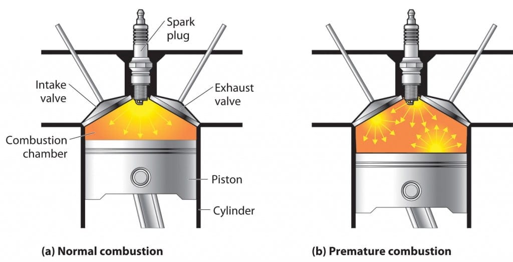
Pre-ignition is a different problem and the distinction matters for diagnosis. Normal combustion starts at the spark plug; the flame front propagates through the charge. Knock occurs after the spark, in the end-gas zone. Pre-ignition starts before the spark, triggered by a hot spot in the combustion chamber, an incandescent deposit, or an overheated valve seat. Pre-ignition operates on a faster timescale and is typically more destructive than detonation. Knock control systems address knock and detonation. If you have pre-ignition, find and eliminate the hot spot.
The root causes of knock are predictable:

Knock sensors are piezoelectric accelerometers bolted to the engine block, each monitoring the frequency band that corresponds to the mechanical resonance of the cylinder bore during a detonation event. That resonant frequency is typically 6–15 kHz and is bore-diameter dependent: larger bores resonate lower, smaller bores resonate higher (per basic acoustic theory, F = 0.9 × c/B, where c is the speed of sound in the charge and B is bore diameter in metres). Your ECU’s knock frequency setting must match your engine’s bore.
The ECU applies a bandpass filter to the raw sensor signal, isolating the knock frequency band from normal mechanical engine noise. The ECU then integrates the filtered signal over a defined crank angle window per cylinder, typically 0–40° after top dead centre (ATDC), when the end-gas is under maximum pressure and most susceptible to autoignition. The ECU compares the integrated value against a calibrated threshold. A value above the threshold triggers a knock event declaration.

Placement determines signal quality. On inline four-cylinder engines, one sensor positioned between cylinders 2 and 3 typically covers all four bores. On V-engines and wide-bore engines, you need dedicated sensors per cylinder bank. The sensor must thread directly into the block on bare metal: no paint, no thread sealant, no gasket. Any material between sensor and block degrades structural coupling and weakens the signal.
Follow the torque specification from your ECU manufacturer. Both Emtron and Link documentation specify sensor torque; over-tightening or under-tightening shifts the sensor’s internal preload and alters its frequency response.

When the ECU detects a knock event above threshold, it applies ignition retard to the affected cylinder, typically 1–3° per event. The ECU continues monitoring that cylinder. With no further knock, timing recovers gradually at a configurable recovery rate. Persistent knock drives timing further back until the event clears.
The key parameters you need to configure in the ECU:
| Parameter | What it controls |
|---|---|
| Knock threshold table | Integration level above which the ECU declares knock (rpm × load) |
| Knock frequency | Centre frequency of the bandpass filter (Hz) |
| Detection window | Crank angle range in which the ECU samples the sensor (° ATDC) |
| Retard per event | Degrees of ignition timing pulled per knock event |
| Maximum retard | Ceiling on total ignition retard the ECU will apply |
| Recovery rate | Degrees of timing returned per engine cycle after knock clears |
Per-cylinder knock control is the correct architecture for high-performance engines. Global retard pulls timing from all cylinders when only one is knocking, wasting power for no protective benefit. Per-cylinder retard isolates the affected bore, applies the minimum correction needed, and recovers timing independently on each cylinder. Emtron and Link standalone ECUs both implement per-cylinder knock control as standard.
Calibration requires the engine on a loaded dyno with data logging running throughout. Work through these steps in order.
1. Set knock frequency. Match the ECU’s bandpass filter to your engine’s bore resonance. This value is engine-specific. Emtron accepts a frequency table over rpm; Link G4X and G5 set frequency per sensor input. If your ECU supports per-cylinder frequency assignment, use it.
2. Establish the noise floor. Run the engine at full load on high-octane fuel with no knock present. Log the peak integrated sensor values across the full rpm and load range. This baseline is the foundation of your threshold calibration.
3. Build the threshold table. Set the threshold 20–30% above the clean baseline at each rpm/load cell. A threshold too low triggers false activations and unnecessary timing loss. A threshold too high lets genuine knock events go undetected — the ECU logs nothing while the engine takes damage. This is not a theoretical risk: a threshold set too conservatively during calibration will filter out real events, particularly at mid-throttle positions and elevated intake air temperatures where the noise floor differs from full-load conditions. An external knock monitor used alongside the ECU during calibration provides an independent signal to validate that the ECU threshold is catching what it should.
4. Confirm detection. Deliberately induce mild knock by advancing timing slightly beyond MBT on a steady-state pull. Verify the ECU registers events and retracts timing. If the system does not respond, the threshold is too high or sensor coupling is poor. Check mounting before adjusting the threshold.
5. Set recovery rate. An aggressive recovery rate snaps timing back quickly and preserves power, but requires confidence the knock cause has cleared. During initial calibration, use a conservative rate. Tighten it once the tune is stable and you understand when and why knock occurs on your specific engine.
Emtron implements knock control as a two-tier retard system: Short Term Retard responds to active knock events cycle-by-cycle; Long Term Retard accumulates a persistent offset based on repeated short-term activity. The SL4 supports one knock input (global mode only); the SL8, KV8, KV12, and KV16 support dual inputs and Individual per-cylinder mode.
Access: Config → Functions → Function Output Setup → Engine Functions → Knock Control, or Utilities → Knock Studio → Knock Control.
| Model | Knock inputs | Available mode |
|---|---|---|
| SL4 | 1 | Global only |
| SL8 / KV8 / KV12 / KV16 | 2 | Individual (per-cylinder) |
Use Individual mode on all performance builds where SL8 or KV hardware is fitted. Global mode pulls timing from all cylinders when only one is knocking — acceptable on SL4 builds, but a compromise.
The filter determines which frequency the ECU analyses. The centre frequency must match your bore’s resonant frequency. Calculate it directly:
F (Hz) = 1,800,000 / (3.14 × bore diameter mm)
| Bore (mm) | Centre frequency (Hz) |
|---|---|
| 80 | 7,166 |
| 85 | 6,745 |
| 90 | 6,372 |
| 95 | 6,033 |
| 100 | 5,732 |
Bandwidth sets the width of the frequency band. Start at 300 Hz and narrow it once you have confirmed the correct centre frequency via sensor logs.
Three filter window types are available:
| Window type | Bandwidth | When to use |
|---|---|---|
| None | Raw digital, no windowing | Strong, clean knock signal; minimal noise floor |
| Hamming | Tight — needs accurate centre frequency | After you have confirmed centre frequency via logs |
| Blackman | Relaxed — centre frequency less critical | Initial calibration on an unfamiliar engine |
Start with Blackman during calibration. Switch to Hamming once you have the correct centre frequency confirmed.
If the engine uses a tuned resonant sensor (resonant at a specific frequency rather than wideband), enable 2nd Harmonic operation — the ECU doubles the analysis frequency to improve signal-to-noise ratio above the noise floor of the base frequency.
Set via the Knock Mode parameter: 0 = Global, 1 = Individual.
Individual mode gives each cylinder its own retard accumulator. A knock event on cylinder 3 does not pull timing from cylinder 1. On engines with variation in port flow, fuel delivery, or intake temperature between cylinders, this distinction matters significantly for power and diagnostics.
Emtron uses two retard layers rather than a single step-per-event model.
| Parameter | What it controls |
|---|---|
| Short Term Retard Gain | Degrees of retard per % above threshold, per detection cycle |
| Short Term Advance Rate | Rate at which short-term retard returns to zero (°/cycle) |
| Short Term Retard Limit | Maximum short-term retard |
| Long Term Retard Gain | Long-term retard applied based on short-term accumulation |
| Long Term Advance Rate | Rate at which long-term retard recovers |
| Long Term Retard Limit | Maximum long-term retard |
Short-term retard handles transient knock events and recovers quickly. Long-term retard accumulates when knock events repeat across multiple cycles — it acts as a persistent offset that recovers slowly. If long-term retard builds on every run and does not return to zero between pulls, the base ignition map is consistently over the knock threshold. That is a tuning problem, not a calibration problem.
| Parameter | What it controls |
|---|---|
| Knock Window Start Angle | Crank angle at which the ECU begins sampling the sensor |
| Knock Window Angle | Duration of the sampling window in degrees |
The window must be shorter than the firing interval for your engine configuration: below 90° for a V8, below 60° for a V12. Start at 10° ATDC with a 30° window and adjust from sensor log data.
Three tables work together:
Knock control disables retard under these conditions — configure each one deliberately:
| Lockout | Purpose |
|---|---|
| RPM Lo Lockout | Prevents retard during idle and low-rpm operation where noise floor is elevated |
| RPM Hi Lockout | Prevents retard above overrun rpm if applicable |
| Post Start Delay | Disables knock control for a set time after engine start (cold noise floor) |
| TP / dTP Lockout | Prevents retard during rapid throttle transients |
| dMAP Lockout | Prevents retard during sudden MAP changes |
On every dyno run: per-cylinder Knock Level, per-cylinder Short Term Retard, per-cylinder Long Term Retard, per-cylinder Knock Count. A cylinder with consistently higher long-term retard than the others is flagging a cylinder-specific problem — fuel delivery imbalance, port flow variation, or a local hot spot.
XTRA Motorsport stocks Emtron KV8, SL4, SL8, and Shadow ECUs, stocked in Lithuania for EU delivery.
Link implements knock control with a single-tier step model: the ECU applies a configurable retard step per knock event and recovers at a set rate. G4X and G5 both support one or two sensor inputs, with frequency windowing configurable per cylinder or per bank. Access: ECU Controls → Knock Control.
Use the same bore resonance formula as Emtron: 1,800,000 / (3.14 × bore mm). Assign frequency per cylinder or per bank. All cylinders in a standard inline engine use the same value. Link does not expose filter window types directly — the filter is set by centre frequency and bandwidth inputs only.
| Parameter | What it controls |
|---|---|
| Knock Retard Table | Degrees retarded per knock event, configurable by rpm |
| Maximum Retard | Ceiling on total ignition retard across all events |
| Recovery Rate | Degrees per engine cycle returned when no knock is detected |
The Knock Retard Table allows different step sizes across the rpm range. Set smaller steps at high rpm — a 3° pull at 7,000 rpm costs more torque than at 3,000 rpm. During initial calibration, use conservative steps (1°) and increase once you understand the engine’s knock behaviour.
Threshold table: rpm × load axes. Set 20–30% above the clean noise-floor baseline from a full-load run on high-octane fuel, same as any platform.
Detection window: configured in degrees ATDC. Starting point: 10° start, 30° duration. PCLink logs the raw knock sensor signal — use it to confirm the window is capturing the knock event and not mechanical noise.
Per-cylinder Knock Level, per-cylinder Knock Retard, per-cylinder Knock Count on every run. PCLink’s knock runtime values display current retard and peak retard per cylinder in real time during a dyno session.
XTRA Motorsport stocks Link G4X and G5 ECUs, stocked in Lithuania for EU delivery.
Knock control is a safety net, not a tuning strategy.
A correctly tuned engine on the right fuel does not activate knock control regularly at wide-open throttle. If your ECU pulls several degrees of timing on every hard run, the base tune is past the limit: the ignition map is too aggressive, fuel octane is insufficient for your cylinder pressure, or there is a mechanical fault — a lean injector, excessive intake air temperature, or combustion chamber deposits.
Persistent knock retard reduces power, raises exhaust gas temperature, and hides the root cause instead of fixing it. Tune around knock control long enough and you will damage the engine. Investigate and resolve the cause.
The diagnostic path is direct:
Yes — and fuel quality change is the most common cause.
Knock control has a maximum retard limit. On Emtron, the combination of Short Term Retard Limit and Long Term Retard Limit defines the total timing the ECU can pull. A typical calibration sets this at 4–8° total. If the engine knocks harder than that limit can manage, the ECU hits its ceiling and cannot protect further. Knock continues. Damage follows.
This rarely happens on the fuel the engine was tuned on. It happens when the fuel changes.
A race engine tuned on 98 RON pump fuel or a specific branded premium — Shell V-Power, Q8 Formula, Progresso 100 — is calibrated with the timing right at the limit for that fuel’s octane rating. The calibrator set maximum ignition advance at every rpm and load cell. There is no safety buffer by design. The target is maximum power, not reliability margin.
Refill that same engine with 95 RON fuel, or 91 RON from a rural station, or a batch from a supplier whose octane rating does not match the label. The knock threshold drops. The ECU retracts timing to its maximum limit. If the gap between what the fuel can tolerate and what the ignition map demands is larger than the retard limit, the ECU runs out of headroom. The engine knocks under load with no further protection available.
OEM engines do not have this problem at the same severity. Manufacturers calibrate with a deliberate buffer — 3–5° of timing held back from MBT — specifically to survive fuel quality variation, altitude changes, and temperature extremes across the production vehicle’s entire lifespan. A race engine has none of that buffer. The calibrator used it all.
The practical rule: use the fuel the engine was calibrated on. If you know you are filling with lower-octane fuel — at a race meeting where your usual brand is unavailable, or in a country where fuel quality varies — reduce ignition timing across the map before running the engine at full load. Do not rely on knock control to bridge the gap.
The most destructive knock scenario is not a brief transient event at medium rpm. It is sustained knock at maximum rpm under continuous high load — held in 6th gear at 8,700 rpm at wide-open throttle on a long straight or a rolling dyno pull.
The reason is frequency. At 8,700 rpm on a four-cylinder engine, the combustion event for each cylinder occurs every 13.8 ms. Knock events at this condition do not arrive one at a time with recovery intervals between them — they arrive at the same cadence as combustion itself. The piston crown has no time to shed heat between events. Each successive knock event deposits additional thermal and mechanical load on a crown that is already at maximum temperature.
The piston crown is the first casualty. Under normal combustion, a thin laminar gas layer sits on the crown surface and acts as a thermal insulator, keeping direct combustion heat from reaching the aluminium. Knock turbulence strips this layer. Combustion gases contact the bare crown surface directly, and localised erosion begins at the ringland — the area under the highest mechanical and thermal stress. Sustained knock at high rpm and load accelerates this: each event erodes material, raises the local crown temperature, and reduces the thermal insulation capacity for the next cycle. The damage compounds. In severe cases the crown perforates — a hole melted or burned through it. Ringland fracture from repeated mechanical shock loading is the other failure path. Either failure releases fragments into the combustion chamber. The connecting rod and cylinder bore follow.
Knock also has a self-reinforcing mechanism that makes sustained events worse than transient ones. Each knock event raises local cylinder temperatures, which lowers the autoignition threshold for the next combustion cycle. Lower threshold means knock occurs more readily on the next cycle, which raises temperatures further. Left unchecked under sustained load, this escalation is rapid — mild knock at the start of a long straight can become severe knock by the end of it, even with no change in throttle position or rpm.
Knock control’s retard limit compounds the problem. With 4–8° of available retard and a retard gain calibrated for transient events, the system can manage brief knock excursions. It cannot manage sustained knock at the engine’s thermal and mechanical ceiling. The retard headroom runs out. If the fuel quality is wrong or the tune was too aggressive for the conditions, the ECU cannot pull enough timing to bring cylinder pressure below the knock threshold. The system is at its limit and the engine takes the difference.
The scenario to avoid: sustained full-throttle operation at or near the rpm limit when fuel quality is uncertain. The rpm limiter does not protect against this — it only caps rpm. Being held at 8,700 rpm under load is identical to briefly touching 8,700 rpm from a knock physics standpoint, except the duration is far longer. If knock is occurring, every additional second at that condition adds cumulative damage.

