

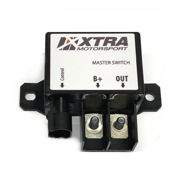
The Motorsport Battery Isolator 150A is an electromechanical battery cut-off relay built to mount directly at the battery, keeping the heavy main power cables as short as possible. Instead of running thick 25 mm² cable all the way to a cabin-mounted rotary master switch, only thin, lightweight trigger wires run to an external emergency kill switch and a separate internal driver on/off switch — the relay does the high-current switching at the battery itself. It is fully potted and sealed from the factory, switches up to 300 A, carries 180 A continuously and works on systems up to 24 V DC, making it a clean, lightweight replacement for a traditional mechanical master switch on rally, hillclimb and circuit cars. Because it isolates with mechanical contacts rather than semiconductors, it suits the general circuit-breaker role that FIA Appendix J defines, where solid-state isolators are not accepted.
Technical Specifications
| Property | Value |
|---|---|
| Type | Electromechanical battery disconnect relay (contactor) |
| Continuous current | 180 A @ 25 °C with 25 mm² (4 AWG) cable |
| High-temperature rating | Derates to ~130 A continuous at 85 °C |
| Switching capacity | Up to 300 A |
| System voltage | Up to 24 V DC |
| Power terminals | M6 studs — Power In / Power Out |
| Mounting / stud centres | 84 mm (M6 stud spacing) |
| Trigger connection | 2-pin AMP connector kit |
| Operation | Continuous (non-latching) — coil energised to hold ON |
| Sealing | Fully potted, IP67 |
| Contact resistance | Minimal — low voltage drop across the contacts |
| Weight | Approx. 0.24 kg |
| Environmental | Heat, moisture, vibration and dust resistant |
What you can do with it
- Switch the full vehicle power path at the battery, keeping heavy cable runs short and light.
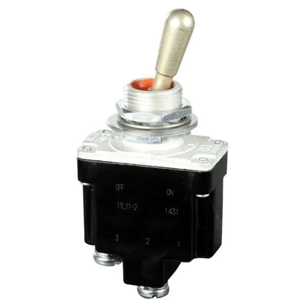
- Trigger the cut-off remotely from an external emergency kill switch and a separate driver master switch using thin, lightweight wiring.
- Add extra kill points — co-driver button, marshal pull-cable — into the trigger loop for redundant safety shut-off.
- Isolate the battery, alternator and ECU together when wired into the main supply line so the car is fully dead when triggered.
- Mount it in the engine bay or boot: full potting makes it resistant to heat, vibration, moisture and dust.
Terminals and wiring
| Terminal | Detail |
|---|---|
| Power In | M6 stud — battery side |
| Power Out | M6 stud — vehicle side |
| Trigger | Low-current 2-pin AMP connector kit, fed from the kill-switch loop |
The relay is non-latching: its coil must stay energised through the kill-switch loop to hold the main contacts closed, so the system draws a small holding current while the car is live. Breaking the trigger loop — via the external emergency switch, the driver master switch, or any additional kill button wired in series — drops the relay and isolates the battery.
Relay vs solid-state isolator
| Aspect | This relay (electromechanical) | Solid-state isolator (MOSFET) |
|---|---|---|
| Switching element | Mechanical contacts | Semiconductors |
| FIA general circuit breaker role | Mechanical contacts accepted | Not accepted |
| System voltage | Up to 24 V DC | Typically 12 V only |
| Built-in alternator run-down | No | Often integrated |
| Relative weight | Heavier (~0.24 kg) | Lighter |
| Relative cost | Lower | Higher |
Accessories
- Motorsport Battery Cable — 25 mm² (4 AWG) cable for the main power path between battery and relay.
- Handle for Battery Cable connector 50 A — battery cable termination hardware.
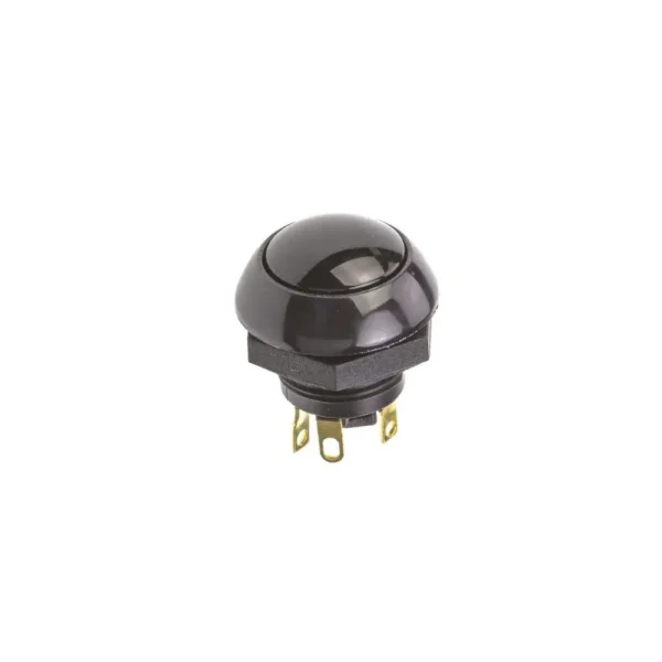
- Push button 15A — suitable for the dash on/off or an additional kill point in the trigger loop.
FAQ
Is this battery isolator suitable for FIA cut-off requirements?
It uses mechanical switching contacts rather than semiconductors, which is what FIA Appendix J requires of the general circuit breaker — solid-state (MOSFET) isolators are not accepted for that role. To form a compliant master cut-off it must be installed correctly: triggered by a compliant external emergency switch and a separate driver master switch, wired so the whole electrical system is isolated. Always confirm the full installation against the current regulations for your championship.
Does it cut the alternator and stop the engine?
Not on its own — and it should not be relied on to do so directly. On a running engine the alternator is still generating, so opening the battery relay alone does not stop the engine and can expose the electrical system to a load-dump voltage spike. The correct method is to use the same remote kill switch to also trigger the ECU or PDM to cut the injectors, ignition and fuel-pump supply. That shuts the engine down first; once the engine stops the alternator stops generating, and the battery relay then safely isolates the system. Wire the kill-switch loop so it commands the engine shut-down and drops this relay together.
Is it latching, or does the coil draw current while the car is running?
It is a continuous (non-latching) relay: the coil must stay energised to hold the contacts closed, so there is a small holding current whenever the car is live. This is normal for a contactor-style isolator and is the trade-off for using mechanical contacts. The car is fully isolated the instant the trigger loop is broken.
What cable size do I need and where should I mount it?
Use 25 mm² (4 AWG) cable as a minimum for ~180 A continuous, and mount the relay as close to the battery as possible so the heavy cable run stays short. Only the thin trigger wires need to reach the external kill switch and the driver master switch.
How is it different from a Cartek-style solid-state isolator?
This is an electromechanical relay with M6 power studs, 24 V capability and mechanical contacts that suit the FIA circuit-breaker role. Solid-state isolators use MOSFETs, are typically 12 V only and often add features such as built-in alternator run-down, but their semiconductors are not accepted as the general circuit breaker. The relay is the simpler, lower-cost, higher-voltage option where mechanical contacts are required.
Does it work on a 24 V system?
Yes — it is rated for systems up to 24 V DC, so it suits both 12 V and 24 V installations.

Reviews
There are no reviews yet.