
How to Build a Motorsport Wiring Loom — Materials, Techniques, and Process
Share:
Share:
By Andrius Kontrimas, Motorsport Engineer — Race Engineer in GT3, LMP3 and 24H Series. Founder of XTRA Motorsport.
A motorsport wiring loom — or race car wiring harness, as it is more broadly known — is not automotive wiring done with nicer wire. It is a different discipline: part electrical engineering, part mechanical design, part material science. The goal is not just to connect devices; it is to do so in the minimum weight, with maximum reliability, in an environment that actively tries to destroy the wire.
This guide covers the complete process: why standard automotive wiring fails in motorsport conditions, how to plan a loom before cutting a single wire, which materials to use and why, the core techniques of professional harness building, and how to test and commission a finished loom.
Key facts: A race car wiring harness requires mil-spec Tefzel wire (M22759/32), Raychem DR-25 sleeving, sealed connectors (Deutsch DTM, Autosport AS Series), and concentric twisting. Plan every circuit before cutting wire. Budget 20–30 hours for a club build and €1,000–€1,500 in materials. Always use a DMC M22520 crimper — a generic automotive crimper does not produce a mil-spec crimp.

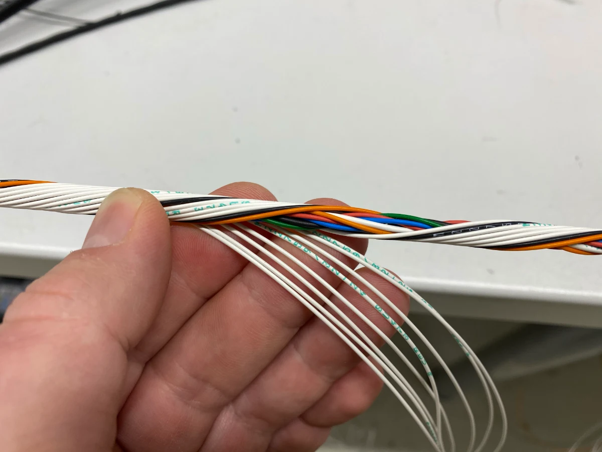
Watch the build process from one of our recent builds:
Standard automotive wire fails in race car applications for three reasons: weight, temperature, and vibration.
A typical road car wiring harness is built for cost, not weight. PVC insulation is cheap, thick, and heavy. In a race car, every gram of unnecessary insulation across hundreds of metres of wire adds up to kilograms of ballast that is doing nothing useful.
The engine bay of a turbocharged race car reaches sustained temperatures that degrade PVC insulation. PVC begins to soften at 70–80°C. A race engine bay regularly sees 120–150°C near the exhaust and turbocharger. PVC-insulated wire in that environment becomes brittle, cracks, and shorts — sometimes immediately, sometimes after several heat cycles.
Road car harnesses are routed and supported for a smooth road surface. Race car vibration is an order of magnitude higher. PVC wire chafing through its insulation at a support point is one of the most common failure modes in amateur-built harnesses.
M22759/32 is the military specification for ETFE (ethylene tetrafluoroethylene) crosslinked wire — the technical specification behind what is marketed as Tefzel wire. It defines: – Conductor construction (stranded, silver-plated or tinned copper) – Insulation material (ETFE, crosslinked for improved temperature resistance) – Insulation wall thickness by gauge – Performance requirements: temperature rating −55°C to +150°C continuous, flame retardant, fuel and oil resistant
M22759/16 is the same specification family in a standard wall variant: thicker insulation than /32’s lightweight wall, slightly heavier and more abrasion resistant. It is equivalent to the Spec44 grade.
Raychem Spec55 (manufactured by TE Connectivity) meets and exceeds M22759/32. It is the benchmark wire for ECU harnesses in professional motorsport. When you see “Tefzel wire” or “mil-spec wire” referenced in professional harness discussions, M22759/32 and Spec55 are the specific products being described.
The difference between a professional harness and an amateur one is usually not the materials or the technique — it is the planning. A professional harness builder works from a complete circuit map before touching the wire.
The circuit map needs to live somewhere structured. The tool you choose determines how quickly you can catch a pinning error, hand the design to another builder, or modify the loom a year after it was built.
Spreadsheets are where most builds start, and for a single-loom club car they are adequate. One row per wire — circuit name, from-connector, from-pin, to-connector, to-pin, wire colour, gauge — is a complete and workable harness document. Free, universally readable, and the same spreadsheet doubles as the test sheet for pin-by-pin continuity checking.
RapidHarness is a downloadable harness design tool built for motorsport and small-volume builds. It generates from-to wire lists, connector face views, and cut lists automatically. Worth the cost for any build that goes beyond a single engine loom.
HarnWare is the professional standard. It carries a full component database including the complete Raychem product range, calculates concentric twisting layer counts for a given wire bundle, and generates manufacturing documentation to aerospace and motorsport OEM standard. If you are building harnesses commercially or managing a library of designs across multiple builds, HarnWare is the correct tool.
Wiring.Studio (by WHY NOT SIA) takes a modern approach to harness documentation and build management. At a significantly lower price point than HarnWare, it is a strong option for builders who want structured harness documentation without the cost overhead of full professional CAD tooling.
Whichever tool you use, the minimum output is three documents: a from-to wire list by circuit, connector face views showing pin assignments, and a cut list by gauge and colour. These three documents are what allow a harness to be serviced or modified by someone other than the original builder.
Write down every electrical circuit in the car. For each one, note: – Load: what device is being powered or signalled – Current draw: continuous operating current in amps – Connector: what connector type is required at the device end – Location: where the device is in the car – Routing: rough path from the source to the load
This list is the foundation of the loom. Do not start before it is complete. A missed circuit means a loom returned to the bench for modification after installation — expensive in time and potentially damaging to the finished harness.
For a standalone ECU installation, the ECU connector pinout drives the design of the engine harness. If you have not yet chosen your ECU, read How to Choose a Standalone ECU before planning the pinout — the connector type and pin count will shape the entire harness architecture. Print the pinout and assign every pin before you start: – Which pins carry injector signals – Which pins carry coil trigger signals – Which pins carry sensor inputs (each sensor gets a dedicated signal and ground return) – Which pins carry power supply and main grounds
Reserve any unused analog input pins for a small spare inputs connector — typically a 6–8 pin DTM, with 0V reference and 5V sensor supply brought out alongside the spare signal pins. You will not know today which sensor you will want to add next season. This costs nothing at build time and eliminates a loom modification later.
Also plan a CAN connector under the dashboard — a 4-pin DTM carrying 12V, GND, CAN High, and CAN Low. This gives you a clean connection point for a dash logger, CAN keypad, or any future CAN device without modifying the main loom.
In a system with a PDM (power distribution module), the wiring architecture changes significantly. Instead of running individual power feeds from a fuse box to each load, the PDM outputs feed each circuit directly. This: – Eliminates individual fuses and relays – Reduces the number of high-current wire runs – Centralises circuit protection and control in the PDM software – Allows CAN-controlled switching (ECU or keypad can enable/disable circuits without additional wiring) – Provides real-time current monitoring and output state logging per channel — you can see exactly what each circuit draws under load, flag a circuit that has increased in draw (a sign of a developing fault), and build a database of real current consumption to inform wire sizing on future builds
Plan the PDM channel assignment alongside the ECU pinout.
The connector choice at each end of the loom defines reliability and serviceability.
| Location | Connector type | Reason |
|---|---|---|
| Under-bonnet, engine sensors | Deutsch DT / DTM | IP67 sealed, vibration-proof, ratchet locking |
| Transmission sensors | Deutsch DTM | Compact, sealed, oil and vibration resistant |
| Pumps | Deutsch DTM | Compact, IP67, suitable current rating |
| Firewall bulkhead | Autosport AS or Deutsch DT | High pin count, secure pass-through |
| ECU connector | OEM-pattern or Autosport | Match the ECU housing |
| Cockpit ancillaries | Deutsch DTM or Autosport | Lighter duty, still sealed |
Do not use unsealed connectors in the engine bay. Do not use Deutsch DT/DTM connectors where Autosport provides a lighter, higher-density option at the ECU end.
At every connector exit, install a heat shrink boot sealed with HellermannTyton V9500 epoxy. Avoid adhesive-lined heat shrink (ATUM, HTAT) under boots in the engine bay: the meltable adhesive can liquefy under sustained engine bay temperatures.
Before cutting wire, physically trace the routes through the car. Identify: – Firewall pass-through points – Areas of high heat — keep the loom away from exhaust, turbocharger, and heat shields – Areas of movement and scrubbing risk — at these sections, plan HFT5000 abrasion-resistant sleeving over DR-25; also add a double layer of DR-25 at every planned zip tie attachment point so mechanics can cut zip ties during service without cutting into the primary harness protection (this is one of the most common harness damage modes in active competition) – Connector ends — plan service loops here: extra wire length before each backshell so the connector can be fully disconnected and moved clear without stressing the conductors – Sleeving transition points where the loom splits into branches
Sketching the route, even roughly, prevents the most common harness problem: a loom that does not reach its destination, or one that routes through a hot zone.
M22759/32 (lightweight wall): The primary wire for most motorsport harness circuits. 0.30mm nominal insulation wall, suitable for ECU signal wiring, sensor inputs, and actuator outputs. Available in 10 standard colours for colour-coded organisation. We stock M22759/32 across 24 AWG to 12 AWG — it is the most cost-effective mil-spec option and a natural choice for club sport and enthusiast builds.
M22759/16 (standard wall): Thicker insulation wall than /32 — more abrasion resistant but slightly heavier. Equivalent to the Spec44 grade. Used where the wire will be exposed to direct abrasion without additional sleeving protection.
Raychem Spec55: A product specification rather than a military standard, but it meets and often exceeds M22759/32. Specified by name in many professional harness contracts. We can supply Spec55 by special order for builds where it is explicitly required. Either is correct for motorsport use; they are functionally equivalent.
The practical difference between M22759/32 and Raychem Spec55 is small for most motorsport applications. Both use ETFE insulation. M22759/32 is the published military standard — any wire labelled M22759/32 has been manufactured to that specification. Spec55 is TE Connectivity’s branded product that meets and in key parameters exceeds /32, including a higher continuous temperature rating (200°C vs 150°C). Either wire is correct for motorsport use. Spec55 is sometimes specified by name in FIA technical documents and by professional harness builders as shorthand for the highest-quality option. For club and enthusiast builds, M22759/32 offers equivalent performance at lower cost — and it is what XTRA Motorsport stocks as standard.
| Wire type | Temp rating | Wall | Use case |
|---|---|---|---|
| M22759/32 (Tefzel, lightweight wall) | −55°C to +150°C | Lightweight | Motorsport ECU harnesses, all engine bay circuits |
| M22759/16 (Tefzel, standard wall / Spec44) | −55°C to +150°C | Standard | High-abrasion runs without additional sleeving |
| Raychem Spec55 | −65°C to +200°C | Standard | Professional motorsport, FIA-grade builds |
| TXL | −40°C to +125°C | Medium | Club / track day builds where cost is a constraint |
| GXL | −40°C to +125°C | Thick | Production car use only |
| PVC standard | −25°C to +80°C | Very thick | Road cars only — not suitable for race engine bays |
For a full engine harness of 100–150 m of wire, the step from TXL to Tefzel is primarily a temperature decision. TXL is rated to 125°C — a turbocharged engine bay near the exhaust manifold regularly runs 130–150°C ambient, leaving TXL with no headroom. Weight saving is a secondary benefit: approximately 8–13 g/m per circuit depending on gauge.
Certain circuits are sensitive to electromagnetic interference (EMI) and must use shielded wire: – Knock sensors: the microphone signal from a knock sensor is in the millivolt range — unshielded wire in an engine bay will pick up ignition noise – Crank position sensor: critical timing signal, susceptible to interference near coil wires – CAN bus: CAN is a differential signal and does not always require shielding — in most installations, a good quality twisted pair is sufficient. That said, some high-specification looms do shield CAN; Bosch Motorsport ABS looms, for example, use shielded CAN wiring as a design standard
M27500 is the mil-spec shielded twisted pair in Tefzel insulation. The shield is a spiral wrap of tinned copper wire over the conductor pair, with an overall ETFE jacket.
CAN bus uses a differential pair — two wires carrying equal and opposite signals. Twisting the pair ensures any interference affects both wires equally and cancels out at the differential receiver. Pre-twisted CAN wire maintains a consistent twist rate, which matters for signal integrity on runs longer than 1 metre.
For builders who want to reduce material cost (at the cost of time), two single wires in different colours can be ordered and twisted by hand on the bench. The result is functionally identical to pre-twisted CAN wire if the twist rate is kept consistent.
DR-25 is the professional standard for motorsport harness heat shrink tubing. Key specifications: – Temperature rating: −75°C to +150°C continuous – Shrink ratio: 2:1 – Flame retardant, resistant to fuel, hydraulic fluid, and engine oil – Available in sizes from 3.2mm (1/8″) to 38.1mm (1.5″) pre-shrink diameter – Full specification: TE Connectivity DR-25 catalogue section (PDF)
DR-25 goes over every branch of the loom. Size the pre-shrink diameter to be 1.5–2× the bundle diameter — this ensures full contact without voids when shrunk.
Other Raychem grades for specific applications:
RT-375: Clear heat shrink tubing used to protect printed wire identification sleeves. Applied over the ident sleeve after shrinking it in place, RT-375 locks the printed label and protects it from abrasion, fuel, and oil. Without it, ident labels on engine harness wiring will be unreadable within one season.
HFT5000: Abrasion-resistant outer coating over the standard heat shrink material — for sections of loom that will experience rubbing against bodywork, chassis rails, or anywhere DR-25 alone would wear through.
HTAT: Adhesive-lined heat shrink (meltable adhesive inside) — provides environmental sealing at firewall pass-throughs and cable entry transitions. Do not use HTAT under connector boots in the engine bay: the meltable adhesive can liquefy under sustained temperatures.
SCL: An adhesive-lined heat shrink with a 3:1 shrink ratio — stiffer in construction than HTAT (which has a 4:1 ratio). The rigid structure makes it better suited for mechanical protection at branch transitions and backshell entry points.
At every connector exit, the wire bundle must be protected where it leaves the backshell. A heat shrink boot covers the transition from connector to loom, preventing water ingress, providing strain relief, and protecting the individual wires at their most vulnerable point.
We stock Raychem and HellermannTyton heat shrink boots in: – Straight profile: for connectors where the loom exits directly from the rear of the connector, in line with the connector axis – 90° moulded profile: for connectors mounted against a surface where the loom must turn at right angles immediately at the connector exit
Before applying V9500 epoxy to bond the boot to the connector backshell, scuff the DR-25 surface at the overlap zone with fine sandpaper — this gives the epoxy a mechanical key. Without surface preparation, V9500 adhesion to the slick heat shrink surface is unreliable.
A missing boot is one of the most common causes of water ingress failure in motorsport harnesses. Treat it as mandatory, not optional.
Roundit 2000 is a wrap-around polyester sleeving — a split-design that installs without disconnecting connectors. The slit along the length allows the sleeving to open and wrap around an existing harness.
It has a long history in motorsport: under FIA Group N rally regulations, cars were required to use their standard production wiring looms. Engineers fitted Roundit 2000 over the OEM loom to provide protection without modification. It remains standard in rally cockpit installations today, and has become a popular solution in club-level drift builds where flexible, retrofittable harness protection is needed.
Used for: – Service areas: lengths of loom that will be disconnected or modified frequently – Re-entry points: where branches rejoin the main trunk – Areas where DR-25 heat shrink cannot be applied because the connector is already terminated
Temperature range: −70°C to +125°C (FR/V0 variants to +150°C). Provides mechanical protection and abrasion resistance. Note: standard polyester Roundit 2000 provides no EMI shielding — the Roundit 2000 Cu EMI variant with integrated copper braid is required if EMI attenuation is needed. The wrap-around design is its key advantage — it installs over a finished loom without deconstructing the harness.
Every circuit must be identified. This is not optional in a professional loom: when a fault occurs two years after the harness was built, the ident sleeves on each wire are how the technician traces the circuit without a wiring diagram.
XTRA ident sleeves are 1.5mm heat shrink that shrinks down to 0.5mm — sized to fit directly over 20, 22, and 24 AWG wire before the connector is terminated. At that size, printed text is not practical; identification works by colour sequence using the MIL-STD-681 colour code (see the colour coding section below).
Apply ident sleeves before connector termination — once the wire is seated in the backshell, the sleeve cannot be installed. At branch points and connector entries, larger printed labels can supplement the wire-level idents for branch identification; protect any printed labels with a length of Raychem RT-375 clear heat shrink to survive fuel, oil, and abrasion.
Wire colour in a motorsport harness is not cosmetic. A consistent colour system means any technician can identify a circuit’s function from the wire colour before reading a single ident. The system only works if it is applied consistently across every build.
This is the colour and ident system we use at XTRA Motorsport.
For power distribution — 12V supply feeds and ground returns — we use two colours:
| Colour | Function |
|---|---|
| BLACK | Ground (0V return) |
| WHITE | 12V supply |
We do not stock red wire in 12, 14, 16, or 18 AWG. Red Tefzel wire in these gauges is significantly more expensive than black or white. Two colours are sufficient for power distribution: black for ground, white for 12V.
Sensor circuits use three colours that identify the function of each wire regardless of which sensor it connects:
| Colour | Function |
|---|---|
| GREEN | 0V sensor reference — ECU or logger sensor ground output |
| ORANGE | 5V sensor supply — ECU or logger reference voltage output |
| WHITE | Signal — sensor output, injector trigger, actuator output |
Green is always the calibrated 0V return from the measuring device — not the chassis ground, not the main negative, the specific ECU or logger pin that is the 0V reference for that sensor’s measurement. Orange is the 5V reference voltage. White carries the signal.
This covers coolant temperature, oil pressure, TPS, MAP, lambda signals, injector outputs, and coil triggers — the same three colours on every circuit, every build.
CAN bus uses dedicated wire colours: RED for CAN-H, BLUE for CAN-L — always a twisted pair. Where a harness carries multiple CAN buses, ident sleeves identify which bus instance (see below).
XTRA ident sleeves are 1.5mm heat shrink that shrinks to 0.5mm — they fit over 20, 22, and 24 AWG wire. At this size, printed text is not practical. Instead, the sleeves work by colour sequence, using the same colour→digit table as MIL-STD-681 (the military standard for wire colour coding, the same system used for resistor colour bands):
| Colour | MIL digit |
|---|---|
| Black | 0 |
| Brown | 1 |
| Red | 2 |
| Orange | 3 |
| Yellow | 4 |
| Green | 5 |
| Blue | 6 |
| Violet | 7 |
| Grey | 8 |
| White | 9 |

Two or three sleeves in sequence form a code. The first sleeve identifies the circuit type or source. The second and third sleeves encode the device number in MIL decimal.
For a PDM with up to 30 outputs (e.g. MoTeC PDM30), the ident code reads:
Examples: Red | Black | Brown = PDM output 01. Red | Red | Orange = PDM output 23. Red | Orange | Black = PDM output 30.
When a technician finds a red-first ident on an unfamiliar harness, they know immediately this is a PDM-controlled circuit — the fault trace goes to the PDM software, not a fuse or relay.
For sensor inputs, the first sleeve uses a colour other than RED — keeping it distinct from PDM outputs at a glance. The second and third sleeves encode the input number using the same MIL digit table. The type-indicator colour for each circuit class is defined in the build documentation; the MIL digit encoding for the subsequent sleeves is always the same regardless of circuit type.
CAN bus wires use the RED/BLUE wire colour pair (Red = CAN-H, Blue = CAN-L). Most race car harnesses carry a single CAN bus, so no ident sleeve is needed beyond the wire colour itself.
On larger projects with six or more CAN devices, a project-level ident on the first sleeve identifies the destination device — so during loom building each wire’s destination is clear before the connector is terminated. This is a build-time aid: once the connector boot is sealed, the idents are no longer visible without cutting the boot open.
This is the key point about the ident system: idents are primarily used while building the loom. They tell the builder where each wire goes, prevent repinning errors, and provide a reference if a connector ever needs to be cut open and repaired or repinned. Once the heat shrink boot is sealed with V9500 epoxy, the idents are enclosed and not visible in normal use. They are preserved for the case where the connector must be serviced — a boot that is cut off cannot be reused, so the decision to cut is not taken lightly.
Wire gauge in a motorsport harness is governed by three criteria: current capacity, voltage drop, and weight. For ECU signal wires — sensor inputs, analog outputs, lambda — 22–24 AWG is correct; current is under 0.5A and gauge is chosen for mechanical flexibility, not current capacity. Injector and coil trigger wires carrying 1–3A use 20–22 AWG. Power feeds require 16 AWG for a 15A fuel pump, 14 AWG for a 20A water pump, and 12 AWG for a 25–30A engine fan. M22759/32’s 150°C rating gives more thermal margin than TXL (cross-linked polyethylene rated 125°C, a different compound from PVC) or standard PVC (80°C) in a dense bundle near heat sources. Size wire to the current and voltage drop requirements of each circuit regardless of insulation type.
The selection of wire gauge involves three competing factors in detail:
Current capacity is the primary constraint. The wire must carry the operating current without exceeding its temperature rating. Tefzel’s 150°C rating means the insulation tolerates the heat generated at rated current with more margin than 80°C PVC or 125°C TXL — this matters in dense bundles where wires heat each other. It is not a basis for reducing gauge: size to the current requirements and voltage drop limits of each circuit.
Voltage drop matters on long power feeds and for precision-timed circuits. A 12V circuit feeding a device drawing 10A through 3 metres of 20 AWG wire will lose approximately 2.0V to resistance across the full round-trip circuit length. For injectors and ignition coils, this has a direct performance consequence: the ECU reads battery voltage through its internal voltage sensor and uses this to calculate injector dead time (the time the injector takes to open before fuel flows) and ignitor dwell time (the charging time for the coil). If the actual voltage at the injector or coil is lower than the voltage at the ECU supply pin, the ECU’s timing tables will be wrong — injectors will deliver less fuel than calculated, and coils will have less energy per spark. On fuel pump circuits, even a 0.5V drop measurably reduces pump flow rate and fuel system pressure.
Weight drives the motorsport bias toward lighter gauges than automotive practice.
Practical gauge reference table for Tefzel wire:
| Circuit type | Typical current | Recommended AWG |
|---|---|---|
| ECU signal (sensor input/output) | < 0.5A | 22–24 AWG |
| ECU signal (injector, coil trigger) | 1–3A | 20–22 AWG |
| Small actuator (solenoid, relay coil) | 3–5A | 20–22 AWG |
| Medium actuator (fan motor relay, pump relay) | 5–10A | 20–18 AWG |
| Starter solenoid (short inrush ~8A) | 8A peak | 20 AWG |
| Power feed — fuel pump (15A) | 15A | 16 AWG |
| Power feed — water pump (20A) | 20A | 14 AWG |
| Power feed — engine fan (25–30A) | 25–30A | 12 AWG |
| CAN bus | < 0.1A | 22–24 AWG |
| Trigger / sensor shielded | < 0.5A | 22–24 AWG (shielded) |
| Battery cable / starter motor | > 100A | 16–25 mm² (non-Tefzel) |
For sensor circuits (coolant temp, oil pressure, TPS, MAP), 22–24 AWG is the correct choice. The sensors draw milliamps; gauge selection is driven by mechanical strength and flexibility, not current capacity.
Grounding accounts for more unexplained faults — intermittent sensor errors, CAN dropouts, ECU resets — than any other single wiring issue. Plan it before cutting the first wire.
Analog sensors (temperature sensors, pressure sensors, TPS, MAP, lambda) must always use the dedicated, calibrated 0V output from the measuring device — the ECU’s sensor ground pin, or the dash logger’s reference ground output. These outputs are filtered and referenced to the device’s internal analog circuit. Connecting analog sensors to the chassis or a general ground bus introduces an offset voltage into the measurement that the ECU cannot correct for.
Digital sensors (wheel speed sensors, hall-effect triggers, CAN-connected devices) have their own ground reference within their protocol — do not connect digital sensor grounds to the ECU analog 0V.
Build the ground chain in the correct order with correct conductor sizing at every link:
All chassis ground attachment points must be mechanically cleaned back to bare metal with a wire brush before the terminal is fastened — paint, anodising, and corrosion all add resistance that accumulates across the ground chain.
Rather than running individual ground wires from every device back to the battery, plan dedicated chassis ground points at three locations:
Front chassis ground point: local branch to engine cooling fan, headlights, and any front-mounted ancillaries.
Cockpit ground point: local branch to PDM chassis ground, dash logger, cabin fan, wiper motor, and all cockpit-mounted devices.
Rear chassis ground point: local branch to fuel pumps, tail lights, and every device mounted in the rear of the chassis.
Each point is a bolted, surface-cleaned chassis terminal. Local branching at these points keeps return wire lengths short and keeps high-current return paths out of the ECU signal ground circuit.
Separate the power distribution into two buses: a clean bus for the ECU, sensors, and precision electronics, and a dirty bus for motors, actuators, solenoids, and anything that switches high current. Solenoids and relays produce voltage transients when switched off — a solenoid de-energising can generate a spike of several hundred volts on the supply line if not suppressed with a flyback diode across the coil. Sharing a supply rail with the ECU exposes the control electronics to these transients.
Running a ground return through the gearbox, differential, or driveshafts creates a current path through bearing races. Sustained current through a bearing race causes electrochemical pitting — the bearing acts as an electrolytic cell. Run dedicated ground wires back to the chassis star point; do not rely on drivetrain metalwork as return paths.
A loose bundle of wires taped together is not a loom. A concentric-twisted harness is lighter, more flexible, more vibration-resistant, and smaller in diameter than the same wires randomly bundled.
When wires are twisted together, they pack efficiently in concentric layers. The spaces between wires in a circular cross-section are minimised, reducing overall bundle diameter by 15–25% versus a loose group. The twisted structure also provides mechanical integrity — vibration affects the bundle as a unit rather than shaking individual wires independently.
Concentric twisting builds in layers with a specific number of wires per layer: – Core: 1 wire – First layer: 6 wires (total: 7) – Second layer: 12 wires (total: 19) – Third layer: 18 wires (total: 37)
Each successive layer twists in the opposite direction to the layer below it. This is critical — same-direction twisting causes the inner layer to unwind as the outer layer is applied.
The twist is applied by hand. A simple jig — two fixed points at the ends of the wire run, with wires anchored at one end and rotated at the other — lets you maintain a consistent twist rate along the full length. Mark the twist direction clearly before you start.
The connector is where most harness failures occur. Poor crimp quality, incorrect tool selection, or wrong termination sequence are the most common root causes.


Autosport connectors come with the backshell as part of the assembly — boots are separate and must be sourced and fitted independently. Assemble the backshell and boot onto the wire before connector termination; the boot cannot be installed after.
Contacts press into the insert face following the manufacturer’s contact application guide for the specific insert pattern.
Crimp — always, for motorsport wiring. A correctly executed crimp with the right DMC tool and die produces a gas-tight cold weld between conductor and terminal: lower resistance, higher pull-out force, and better vibration resistance than solder. Solder joints introduce a hard boundary between the flexible wire and the rigid solder mass; under vibration, the wire fatigues and breaks at that boundary. Solder has no place in motorsport connector termination.
After every crimped terminal is installed, pull it by hand. A correctly seated terminal in a correctly crimped connection will not pull out under reasonable hand force. If it pulls out, remove it, reinspect, and re-crimp. Do not install a connector with a terminal that moves.
Test continuity pin-by-pin before installing the heat shrink boot. At this stage, contacts can still be removed, repositioned, and reinserted. Finding a pinning error here takes 2 minutes to correct. Once the boot is applied and shrunk, correcting a pinning error requires stripping the boot — which cannot be reused.
The sequence of finishing operations matters. Applying steps out of order means materials cannot be installed correctly.
Do not rush the heat gun. Move slowly and evenly along the tube, allowing full shrink before moving on. Incomplete shrink leaves voids where moisture can collect. The finished DR-25 surface should be smooth with no bubbles or partially shrunk sections.

At every connector, build 50–100mm of extra wire length into the loom routing just before the backshell. This allows the connector to be fully disconnected and moved clear without placing stress on the conductors or crimped terminals. Without service loops at connectors, repeated removal during setup and race weekends fatigues the wires at the terminal crimp — the weakest point in any circuit.

At every planned zip tie attachment point, apply a double layer of DR-25, or a short outer sleeve of DR-25 over the finished loom before installation. When mechanics need to cut zip ties during service, this outer layer takes the blade. Cutting through the primary DR-25 to the wire bundle is one of the most common harness damage modes in active competition.
Use a grommet or a sealed firewall connector (Deutsch or Autosport bulkhead mount). Run the loom through the grommet and seal around it with fire-resistant silicone sealant. The pass-through must be sealed — a hole in the firewall is a fire risk and allows fumes into the cockpit.
A race car wiring harness requires three sequential tests before first power-on: a pin-by-pin continuity check against the circuit map (catches wrong pinning, crossed wires, and shorts between adjacent pins), an insulation resistance test at 500V DC (finds damaged insulation invisible to a standard continuity tester), and a CAN bus termination measurement confirming both 120Ω end resistors are present. Run them in that order — continuity first while connectors are still accessible for correction, insulation resistance before power is applied, CAN check with all devices disconnected. A harness that passes all three before installation will not develop wiring faults on its first run.
Do not assume the harness is correct because it looks correct. Test before installation, and test again on the bench if anything is modified during installation.
Create a test document that lists every wire by its circuit identification: the two connector pins it connects, the expected resistance (near zero for a direct wire run), and a checkbox for pass/fail. Work through the entire loom systematically. This catches wrong pinning, crossed wires, and shorts between adjacent pins.
A megohmmeter applies a high voltage (typically 500V DC) between conductors or between conductors and the shield/ground, and measures the insulation resistance. A good wire should show greater than 100 MΩ. A value below 10 MΩ indicates damaged insulation, contamination, or a short path. This test will find insulation faults that a continuity tester cannot see.
If the car is fitted with a PDM: 1. Enable PDM channels individually in the PDM configuration software 2. Enable the ECU power channel first — verify the ECU powers up and shows no faults 3. Enable sensor supply channels — verify correct voltage at each sensor connector 4. Enable actuator channels (injectors, coils) — verify the ECU can command each output 5. Enable ancillary channels (fan, pump, solenoids) — verify each device operates
Never apply power to an untested harness with all channels active simultaneously. An error in a single circuit can cause damage to multiple devices if the fault is across a power rail.
The CAN bus requires 120Ω termination resistors at each end of the bus. With the bus powered down and all devices disconnected, measure resistance across the CAN Hi and CAN Lo wires at each connector. You should measure 60Ω (two 120Ω resistors in parallel). If you measure 120Ω, one terminator is missing. If you measure below 40Ω, there is an additional resistor somewhere on the bus, or a short.
The boot must be installed on the wire before the connector is terminated. If you have already seated the terminals, the only way to install the boot is to remove all contacts from the connector, slide the boot on, and repin — possible but wasteful and a risk to the contacts. Check the boot is in place before you pick up the crimper.
The shield drain wire in a shielded pair must be connected at one end only — at the ECU end. Connecting the drain at both ends creates a ground loop that actively induces interference. Note that the drain wire must be carried through the firewall connector as a dedicated pin — do not earth it locally at the bulkhead. Plan the drain pin assignment when designing the firewall connector pinout.
Every connector needs 50–100mm of extra wire length before the backshell. A loom built tight to the route with no service loops at connectors cannot be disconnected and reconnected repeatedly without fatiguing the wires at the terminal crimps. Plan this at the routing stage, not at the bench.
It cannot be done. The sleeve must be on the wire, in its correct position, before the terminal is crimped. Write this in your build checklist and check it before picking up the crimper.
A generic automotive ratchet crimper does not produce a military-specification crimp on Deutsch contacts. The DMC M22520 family of crimpers and the correct die set for the terminal type is the correct tooling. Using incorrect tools produces crimps that may appear correct but will fail under vibration or thermal cycling.